Taper Pin Features
- Huyett Marketing Department
- 03/08/2021
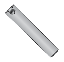
Taper pins are arguably one of the simplest pin designs available, and along with dowel pins, are the oldest. Taper pins are turned from barstock to varying tolerances depending on the specification. This production technique is slower than the heading and grinding process used to manufacture dowel pins and slower than rolling steel pins.
Design Considerations
Taper Pins
Standard taper pins are used as positioning components for transmitting low torques
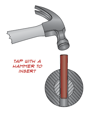
Pound a punch or drive tool into small end to remove
Externally Threaded
Threaded taper pins are used in blind holes
Removal is achieved by screwing a nut down onto the threads
Taper Pins
Internally threaded for use as a pull dowel
Designations

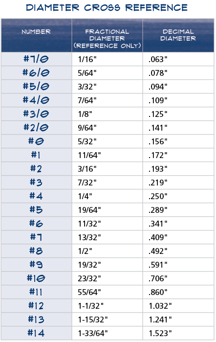
The number refers to the diameter of the large end of imperial pins. To get the diameter of the small end, multiply the length by .02083 and subtract from the decimal size of the large end.
Taper
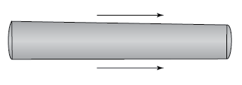
ASME B18.8.2 specifies a taper of 1/4" per foot (0.02083" per inch)
Microfinish

A 63 microfinish is standard to allow smooth insertion
Easy Installation
How Standards Help Manufacturers
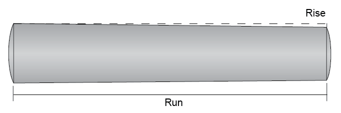
Tapers are expressed in terms of rise over run. In other words, the amount of taper is stated per linear units of measure. A 1/4" taper per foot means that for every 12" in linear distance (run) the thickness of the part (rise) decreases by .25" (1:48). Metric pins decrease by 1 mm for every 50 mm (1:50).
Taper Pin Types
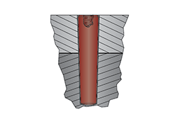
Standard
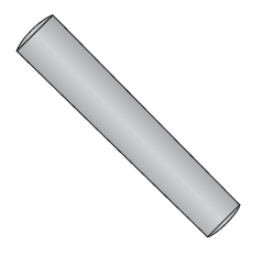
Simply designed pins that are hammered or driven into a tapered hole. 1/4" taper per linear foot.
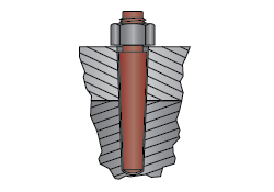
External Thread
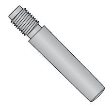
External threads are used when a tapered pin has to be removed from the driven (large) end. Tightening a nut on the threads will unseat the pin.
Design Considerations
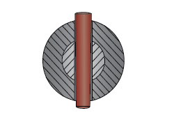
Step Drilling Taper Pin Holes
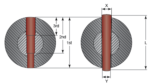
Left: Step Drilled Hole Right: Installed Pin
To obtain diameter of small end (Y), multiply length (L) by .02083 and subtract from large end (X).
If a helically fluted taper reamer is used, the diameter of the small end of the pin is the size for the through drill.
Step drilling and using straight fluted reamers have specific requirements. Call for details.
Always test step‑drilled holes for verification prior to production.
Quick Reference Guide
Taper pins are a highly precise locating pin. The taper causes constant contact through the length of the pin as well as the entire cross section, creating exceptional holding power. It also allows for a repeatable firm seat and exact location when reinserted after disassembly.
Taper
Common Names: Taper Pin
Applicable Standards: ASME B18.8.2*, MS 24692, AN 386, DIN 1, DIN 7977 (external thread); DIN 7978 (internal thread)
* Not applicable to Standard Taper Pins sizes #11 - #14
How to Identify: Nominal diameter x nominal length; The nominal diameter of imperial pins is called out by a number used to signify the dimension.
Fabrication: Turning, thread rolling (if threaded)
Common Uses: Low torque positioning and locking. Often found on printing presses and other large mechanical assemblies. Mostly used in original equipment.
Comments: The diameter of imperial pins is measured at the large end. Metric pins are measured at the small end.
Applications
Taper Pin Use
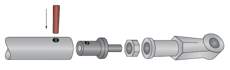
Taper pins are used to align and hold assembly components together
External Threaded Taper Pin Use
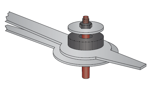
External threaded taper pins are used to hold a clock hand mechanism together
Internal Threaded Taper Pin Use

Internal threaded taper pins are used in applications where a flush surface is desired